Machine Recycling Discussion and Moderated Newsgroup > Full Machines
> Complete Machines
> Woodwworking
> South
> New
> Edc electronic devices corporation dc calibrator 521
Edc electronic devices corporation dc calibrator 521
Link to Manual /htm/ServiceSupport/PDF/.../521%20Manual.pdf
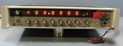
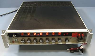
Up for sale is one USED Electronic Devices Devices 521 DC Calibrator 521
Has voltage and current capability!!
Has rear connectoprs for output and IEEE connectors, both are unverified!!
SOLD ASIS NO WARRANTY NO RETURN!!!!
Limit Of Error (or Worst Case) methods.
E Mode: (0.002% of setting + 0.0005% of range)
I Mode: (0.005% of setting + 1 A) compliance with variable control)
Accuracies based on one full year calibration cycle and conservatively specified by using the "Limit-Of-Error" (or worst case methods).
Magnitude is maintained during polarity changes, function changes and range changes in the manual mode. I.e., this eliminates the requirement of reentering the magnitude.
3 voltages ranges (1ppm resolution or 6 decades):
Programming: Integrated microprocessor, GPIB interface. Local and remote control.
The control logic is microprocessor based.
True bipolar control with balanced zero.
A crowbar zero reference may be selected.
Floating Output: Optically isolated between analog output and digital input lines.
Calibration of DVMs, DMM, meters, chart recorders, A/D converters, ATE, monitors, controllers, logging
Linearity check of amplifiers and function modules.
Simulation of thermocouples and strain gages.(4mA to 20mA and 10mA to 50mA) + other transducers.
Note: Compliance voltage up to 100Vdc.
Imbedded Standard for ATE and Data Logging Systems.
Crowbar Indicates selected/programmed short of terminals.
(Relative to N.I.S.T. Standards) The Accuracy statement is based on the Limit-of-Error (or worst-case ) method. All other specifications noted hereafter, which affect accuracy, e.g., line, load, temperature*, drift changes are included in the accuracy statement. Thus, all other specifications are listed as *non-Additive and are indicated * below.
(0.002% of setting + 0.0005% of range + 3 V)
1000Vdc Range: (0.004% of setting + 0.001% of range)
Note: The +3 V specified above applies primarily to the 100mV range where measurements at these low levels should be stated conservatively. It become insignificant on the higher ranges. Notice: The accuracy statement above, based on the Limit of Error method is VALID FOR ONE YEAR calibration cycles.
Stability (*non-additive): 8 hrs, 0.00075%; 24 hrs, 0.001%;90 days, 0.0015%; 1 year, 0.002%.
Line And Load Regulation: 0.0005% from no load to full load and/or for a 10% line fluctuation.
**Compliance Voltage Limit Control: The Compliance voltage may be limited via a manual control. The limits are 100V, 46V, 32V, 18V, 4V, 1V.
Accuracy: (See definitions under voltage mode) [0.005% of setting + 1 A].
Stability (*non-additive): 8 hrs, 0.001%; 90 days, 0.0015%;1 year, 0.002%.
Line & Load Regulation (*non-additive): 0.0005% for a 10% line fluctuation and from short-circuit to full compliance.
Remote Programming is included. It conforms to the IEEE-488.1 convention, designated GPIB and is classified as a Listener and a Limited Talker .
The selected bus address is announced on the front panel display at initialization of the instrument.
Local/Remote Mode is controlled by the operator not the control device. i.e., computer, P, etc. If the 521 is addressed in local the flag response will indicate a device-not-present status. Bus address is set in binary codes on a 5 dip-switch located on the rear panel. Programs written for older series of the 521 as well as the 520 and 501 are compatible with this latest instrument.
Local Mode: Local control is easily established, by the operator, via a front panel switch. (The instrument does not have to be powered-off to establish local control).
The front panel controls duplicate all the programmable functions:
Isolation: Power transformer to analog output, 2.5 104M ohms, 300pF; Control logic to analog output, optically isolated; 109 ohms, 130pF, 500Vdc.
Temperature Coefficient: Ambient, 0.0005%/ C; operating limit, 0.001%/ C.
Switching & Settling Times: Step changes, 5 milliseconds; range changes, 300 milliseconds.
Protection: Voltage mode, Short-circuit and overload protection; current mode, open-circuit protection; front panel enunciator will indicate malfunction condition; recovery is automatic.
Mounting: Rack mounting facilities standard 19 inches; 482.6mm and for bench use with convenient (and removable) tilt bale. (INCLUDED).
Power Requirements: 50 watts; 115V or 220Vac 10%; 50Hz/60Hz.
Ambient (limit-of-error), 20 C to 30 C
Operating Limit, 10 C to 50 C
Dimensions: 19" (48.3cm) wide, 3.5" (8.9cm) high, 18" (45.8cm) deep.
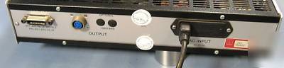
Output Terminals are mounted on the front and rear panels in the following configurations:
Rear Panel Mounted Output Connector must be used for rated output performance.
This is a MIL Spec connector providing connections for high and low output, sensing (four terminal output) and case ground. A pair of binding posts are installed for 1000Vdc range, when the Option RA-5 is ordered.
Front panel mounted outputs are available for monitoring.
Program (digital) Connector mounted on the rear panel conforms to the specifications of the GPIB (1978).
RA-5 1000Vdc Range: Resolution, 1mV, output current, 5mA; accuracy, (0.004% of setting + 0.001% of range).
RA-7 1.0Vdc Range: Resolution, 1 V, output current, 100mA; accuracy, (0.002% of setting + 0.0015% of range + 3 V).
Auxiliary Instrument Model PCS-2B: Programmable 10 Ampere Current Calibrator. This is a building block chassis which operates in conjunction with the Model 521/RA5.
Lab Windows and Lab View drivers are available for direct downloading from National Instruments at .
Note: Drivers for Krohn-Hite Models 521/RA5 and 522 are listed under 520A .
CAB-005: Cable, Two Conductor Shielded Balance Line
CAB-018: Cable, Multi-stacking Double Banana plug
CAB-023: Cable Set, Low Thermal EMF Retractable Banana
CAB-024: Cable Set, Low Thermal EMF Spade Lug