Machine Recycling Discussion and Moderated Newsgroup > Components
> Wheels and Bearings
> West
> Linear amplifier dual 4-1000’s
Linear amplifier dual 4-1000’s
Linear Amplifier Dual 4-1000 s
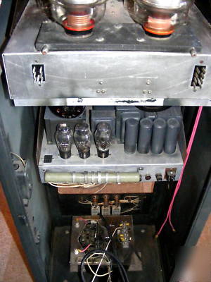
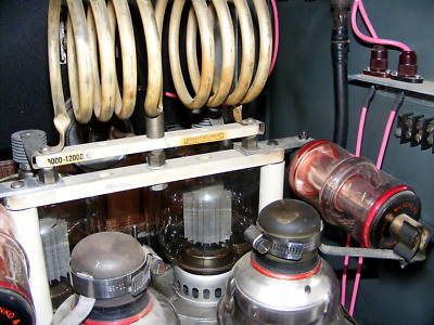
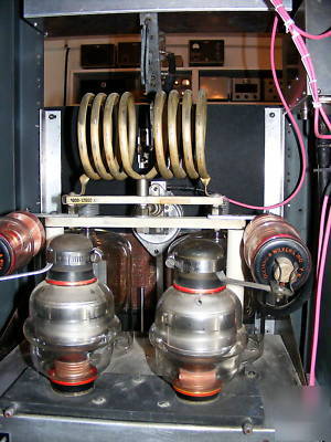
The basics tested all the tubes. The 4-1000 s have been tested in a working amplifier. All vacuum caps have been hipoted same for the HV power supply caps. I think the original design used 3B28 s and was later converted to brick diodes. Everything I could hipot I did including the filament transformers. The bias supply was cleaned up and wiring tested and relaced. The bias voltages were all checked and operate as required.
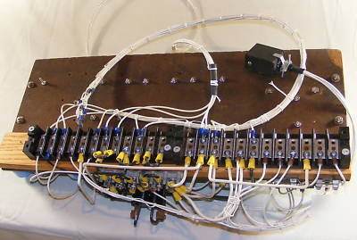
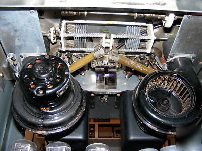
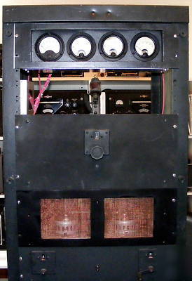
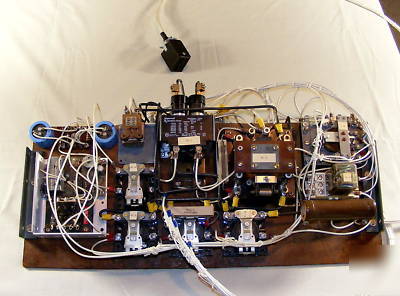
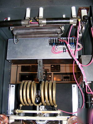
I designed a new control circuit with all the modern refinements. Step start, transmit keying from a modern transceiver control timing on switching bias and HV along with the antenna relay. This is high current stuff so the relay board is a stout design. Again, all of this is fully documented. I completely reworked the meter box with all new 40KV HV wire and shielded the meters. You can see all the pink wire. I am including another 20ft. The HV Power Supply deck needs to be rewired. About a 1 hour project. The big resistors are bleeders and HV ground lift resistors.
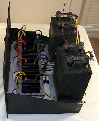
I built a Plexiglas table for the transformer to provide proper I/O voltage terminals. Not pretty but it works.
Some of the coils have been stabilized with a black corona dope.
Both input and output coils are supplied I ll post additional pictures at the URL below.
http:// /for_sale/for_sale_list_8.html
Fans look rusty but run quiet. Nothing wrong with them.
Includes CW/SSB control Switch
Includes DF10000 HF Low Pass Filter 10KW
Some of the small panels are missing in the pictures these are supplied.
New Sheet metal is available for the back (supplied)
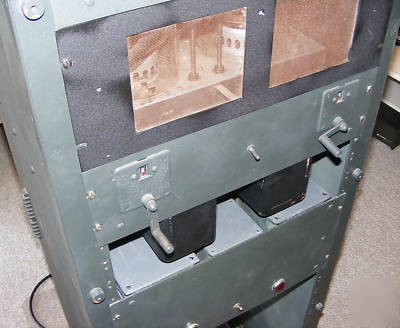
Front plate allows you to view the 4-1000 s
Rewire the HV deck discussed above.
Final Assembly of all subsystems
Fire up as you would any refurbished High Power Amplifier.
Why I have not completed the project:
I have too many projects between work and family and I do like to talk on the radio. You can see the dust from setting. I moved it into the center of my shack 8 months ago with the idea that if it was setting there I would complete it - after all 95% has been done.
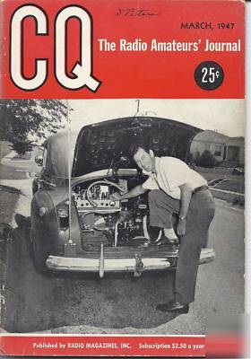
Remember way back when we heard about the California kilowatt amplifiers. Well, this is the Texas Kilowatt amplifier designed by Joe Patterson W5EHM (SK) from San Antonio, Texas. He was well known in the ham community world wide. I have included a picture of him from the 1947 CQ magazine. He is showing a mobile 250 watts on 20Mc and 50Mc with a gas generator in the trunk (I know strange frequencies but that s what the article said.) At probably 12 or 13 years old I was with group of young hams were invited to Joe s house. Joe was a first rate engineer and this amplifier deserves a place of honor in a ham home. He was also a big Collins Radio supporter.
It is big and heavy how do you get it to where you are?
This is not a project for a novice unless you are paying an expert to bring it up.
In the next few days I will be posting additional pictures here: